RTD Basic Principle
An RTD (resistance temperature detector) is a temperature sensor that operates on the measurement principle that a material’s electrical resistance changes with temperature. The relationship between an RTD’s resistance and the surrounding temperature is highly predictable, allowing for accurate and consistent temperature measurement. By supplying an RTD with a constant current and measuring the resulting voltage drop across the resistor, the RTD’s resistance can be calculated, and the temperature can be determined.
RTD Materials
Different materials used in the construction of RTDs offer a different relationship between resistance and temperature. Temperature sensitive materials used in the construction of RTDs include platinum, nickel, and copper; platinum being the most commonly used. Important characteristics of an RTD include the temperature coefficient of resistance (TCR), the nominal resistance at 0 degrees Celsius, and the tolerance classes. The TCR determines the relationship between the resistance and the temperature. The single most common value is 100 ohms at 0°C. The DIN 43760 standard temperature coefficient of platinum wire is α = 0.00385. For a 100 ohm wire, this corresponds to + 0.385 ohms/°C at 0°C.
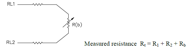
wire construction is the least accurate of the 3 types since there is no way of eliminating the lead wire resistance from the sensor measurement. 2-wire RTD’s are mostly used with short lead wires or where close accuracy is not required.
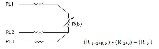
wire construction is most commonly used in industrial applications where the third wire provides a method for removing the average lead wire resistance from the sensor measurement. When long distances exist between the sensor and measurement/control instrument, significant savings can be made in using a threewire cable instead of a four-wire cable.
wire construction is used primarily in the laboratory where close accuracy is required. In a 4 wire RTD the actual resistance of the lead wires can be determined and removed from the sensor measurement.
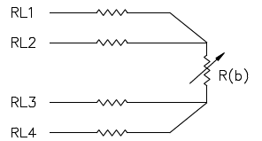
The 4-wire circuit is a true 4-wire bridge, which works by using wires 1 & 4 to power the circuit and wires 2 & 3 to read. This true bridge method will compensate for any differences in lead wire resistances